Where Does a Meter Go in a Circuit? Through or Across
Root Concept
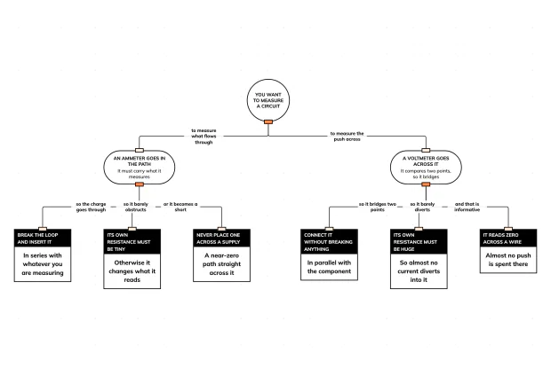
An ammeter measures what flows through a point so it must be placed in the path, in series, with a very low resistance of its own; a voltmeter measures the push used up between two points so it must bridge them, in parallel, with a very high resistance.
CodePLU Goal
Upgrading Human Mental Models
Learn how to think in Workflows

Concept Development By codeplu.com
The two columns are not two devices to memorise. They are one question — does this quantity pass through a point, or exist between two of them — answered twice.
Two Meters, and One Question That Decides Both
This track has made several claims that rest on measurements: the current is the same everywhere in a series loop, the push divides between two bulbs, the branch currents in a parallel circuit add up. Every one of those is checkable, and checking them needs a meter in the right place.
There are two meters and they connect in opposite ways. An ammeter is wired INTO the loop, which means breaking the circuit and inserting it so the charge passes through it. A voltmeter is wired ACROSS a component, touching one side and the other without breaking anything at all. Swapping them over does not simply give a wrong reading — it ruins the circuit, and in one direction it is genuinely dangerous.
That sounds like two rules to remember, and it is really one question asked about each quantity. **Current is something that passes through a point.** To measure what passes through, you have to be in the way of it — hence in the path. **Voltage is the push used up between two points**, which is a difference rather than a flow, and you cannot be "in the way" of a difference. You have to touch both ends and compare — hence across.
Everything else about the two meters follows from that, including the strange requirement that they have opposite resistances. A good measurement must not change the thing it is measuring, and what counts as not changing it is the exact opposite in the two cases.
Why Each One Connects That Way
Why must an ammeter be in the path?
Because it counts the charge that goes through it, and it can only count what actually passes. An ammeter placed beside a component, bridging it, is not in the route the charge takes, so it has nothing to count — in the same way that a turnstile set up next to a doorway records nobody. Inserting it means breaking the loop and wiring it into the gap, which is why using one takes more work than a voltmeter does. In a series circuit it can go anywhere in the loop and read the same value, which is itself a result worth checking; in a parallel circuit where you put it decides whether you are reading one branch or the total.
Why must a voltmeter go across?
Because voltage is a difference between two places, not a thing that travels. Asking "what is the voltage here" is like asking how steep a hill is at a single point with no second point to compare against — the question needs two ends. A voltmeter therefore has two leads that touch either side of the component and report how much push was used up getting charge from one side to the other. That is why it can be connected to a live circuit without breaking anything: it is not joining the route, it is observing from beside it, which also makes it much the easier meter to use in practice.
Why do the two meters need opposite resistances?
Because each must avoid disturbing the quantity it reports, and the disturbance it has to avoid is different. An ammeter sits in the path, so any resistance it has is added to the circuit and reduces the very current it is trying to measure — it must therefore have as close to zero resistance as possible. A voltmeter sits beside the component, creating a second branch, so any current that flows through the meter is current diverted away from the thing being measured — it must therefore have an enormous resistance so that almost none does. Low to avoid obstructing, high to avoid diverting. Same principle, opposite requirement. Neither value is arbitrary; each is forced by where the meter sits.
What happens if you connect them the wrong way?
A voltmeter placed in series is the harmless mistake: its huge resistance is now in the loop, so almost no current flows and the circuit stops working. Nothing is damaged and the bulb simply fails to light. An ammeter placed across a supply is the dangerous one. Its resistance is almost zero, so connecting it directly across a battery creates a path with nothing to limit the current — which is the definition of a short circuit. A very large current flows, the meter can be destroyed and the battery becomes hot. The asymmetry is worth remembering: one error stops the experiment, the other ends it. That is also why the current setting on a multimeter is the one with a fuse behind it.
Real World Example
Three Readings That Settle Earlier Claims
The point of knowing where a meter goes is that it turns the claims of the last four tutorials into things you can confirm.
Step 1
The same ammeter reading at three points in a series loop
Break the loop before the first bulb, read it, then move the meter between the bulbs and read again, then after the second. The three numbers match. That is the single most important measurement in basic electricity, because it kills the idea that current is consumed — the model that predicts a falling reading simply fails here. It takes two minutes and it settles something that an argument alone never quite does, which is why this measurement is worth making rather than reading about. A prediction that fails in front of you does more than a correct sentence ever will.
Step 2
Two voltmeter readings that add to the supply
Put a voltmeter across one bulb of a series pair and then across the other, without breaking anything either time. On a 3V supply the two readings come to roughly 1.5V each and add to about 3V. That is the sharing from the second tutorial made numerical, and it is the measurement that separates voltage from current for good: the two readings differ from each other in a parallel circuit and add up in a series one, while the current does the reverse. Two quantities that behave oppositely in the same circuit are hard to keep confusing once you have seen both readings.
Step 3
A voltmeter reading almost nothing across a wire
Place a voltmeter across a plain connecting wire and it reads close to zero. That looks like a failed measurement and is actually a result: almost no push is used up getting charge along a good conductor, which is exactly what the resistance tutorial claimed and why wires are chosen for low resistance. Do the same across a long thin wire and the reading rises slightly, which is the same claim confirmed from the other direction. A reading of nearly nothing is still a reading, and here it is the one the argument predicted. Wires are supposed to read nearly zero.
FAQs
Final Words
The two meters connect in opposite ways because they measure different kinds of quantity. Current passes through a point, so an ammeter has to be in the way of it, wired into the loop. Voltage is the push used up between two points — a difference rather than a flow — so a voltmeter touches both ends and compares, bridging the component without joining the route.
Their resistances are opposite because a measurement must not change what it measures. An ammeter sits in the path, so its own resistance would reduce the current it reports: it must have almost none. A voltmeter sits beside the component, so any current through it is stolen from the thing being measured: it must have an enormous amount. Low to avoid obstructing, high to avoid diverting.
That is the whole of basic circuits. The next track goes somewhere no circuit can reach — inside the nucleus, which chemistry opened and then said it could not change.
Continue This Track
This concept is part 5 of More Than One Path.
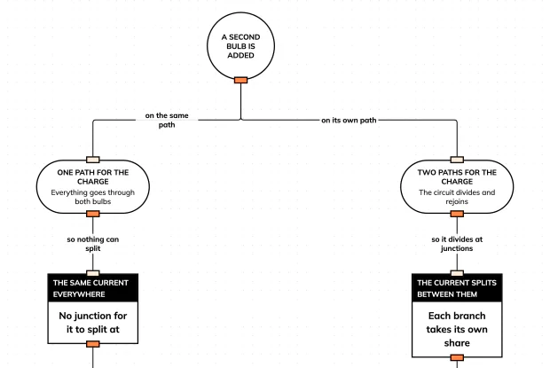
What Happens When You Add a Second Bulb?
Add a bulb to a working circuit and it either dims both or changes nothing. Find out what you actually decided when you connected it, in an interactive playground.
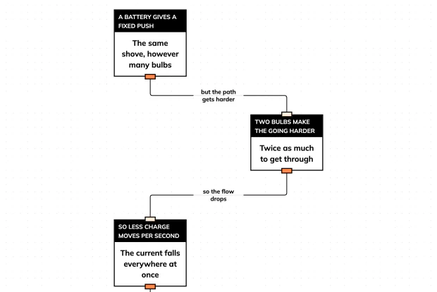
Why Are Bulbs in Series Dimmer?
Two bulbs on one path are both dimmer, and the obvious explanation is wrong. Follow what actually changed, in an interactive playground.
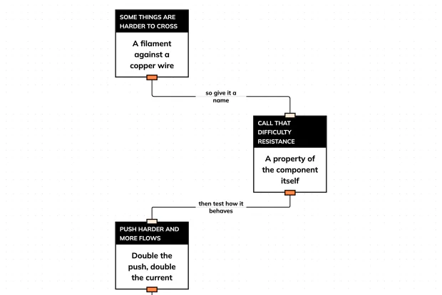
What Is Resistance? And What V = IR Actually Claims
Resistance is the word for how hard a component is to get through — and the equation everyone memorises is a claim about the world. Find out what it asserts, in an interactive playground.
Why Is Your House Wired in Parallel?
Switch on a kettle and the lights do not dim. That is not an accident of good wiring — it is a consequence of one decision. Trace it in an interactive playground.
Where Does a Meter Go in a Circuit? Through or Across
An ammeter goes in the loop and a voltmeter goes beside it, and the reason is the same reason a good measurement must not disturb what it measures. Sort them in an interactive playground.